"Specialists in American Flyer Trains & S-Gauge Railroading"
888-708-0782 (from US only)
978-465-8798 (International)
Phone calls: 2-5 PM Eastern
Time, Tue-Thu only
IMPORTANT NEWS (4-16-2024)
First----RUMORS have been rampant the past few months, even in print, that I've already retired....that I'm out of business......that I'm ill.....and even that I died ! Paraphrasing Mark Twain----" Reports of my passing are greatly exaggerated ! "
Second----Sorry for the continued delay in filling orders.
I cannot keep up with the volume of orders coming in. It has been like this since March, 2020 (COVID time). If you’re not aware, this is a one-man business; I do absolutely everything myself. And to anticipate a suggestion…..“No”….hired help is not possible………training would be self-defeating, and nobody within 50 miles or more would have the needed AF parts knowledge to do this. I’d be spending all my time training and supervising.
This is not to complain or make excuses.………this is just a statement of fact, especially for those newer customers who aren’t aware of my situation. I do this out of a love for the hobby, for American Flyer trains, and for S-gauge in general. Thank you for your business, and for your patience. I appreciate it.
Finally.... It is my current intention to close my business on December 31, 2025. Over the next 18 months, I plan to work on liquidation of most all of my NON-PARTS inventory via periodic website reduced-price sales, as well as auction consignment. The AF Parts portion of my business is not included. It is my hope to offer that portion of the business for sale intact to someone capable of continuing the parts business past 2025.
More information as time progresses, including announcements of periodic website sales. Look for those here, and on my FaceBook page.....hopefully starting later this month (April, 2024).
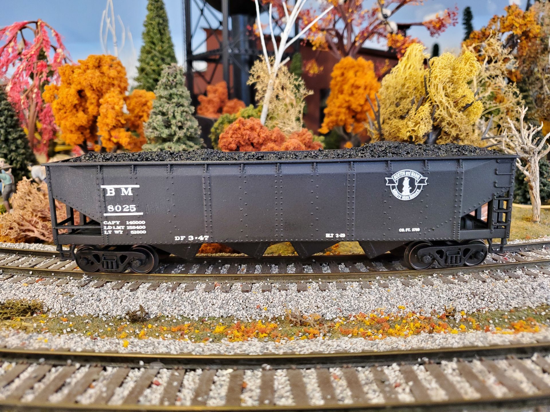
The Bristol S-Gaugers are celebrating their 75th Year Anniversary milestone by offering B&M Quad Hopper cars featuring the "Minuteman" herald which are being produced by American Models. Photo to the upper left is identical to the production cars, except for car number. These car models are available with three different car numbers (8000, 8248 and 8323). These numbers are from the March 1929 and February 1930 range from 8000-8999. The original 1929 quad hoppers were later "re-shopped" with the "Minuteman" herald from the 1940's.
Each car number is available in either scale or high-rail. Due to limited quantities, we reserve the right to fill orders for either one or two cars with car numbers of our choosing. Orders for three cars will receive all three car numbers. Cars are $55 each, plus shipping.
Go to bsgr.us to download and print the Order Form.
OFFER GOOD WHILE SUPPLY LASTS (Only 162 total cars produced)!
SEARCH BAR TIP: The website SEARCH BARS search the entire website for whatever you enter. However, once you get to any CATEGORY product list page, use CTRL-F (find), and you will see a new SEARCH BAR appear near the top. That one searches only the page you are on. Repeat for any additional pages in that Category. This will save you lots of time!
Welcome to Port Lines Hobby Supplies
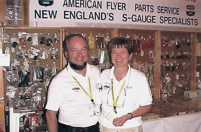
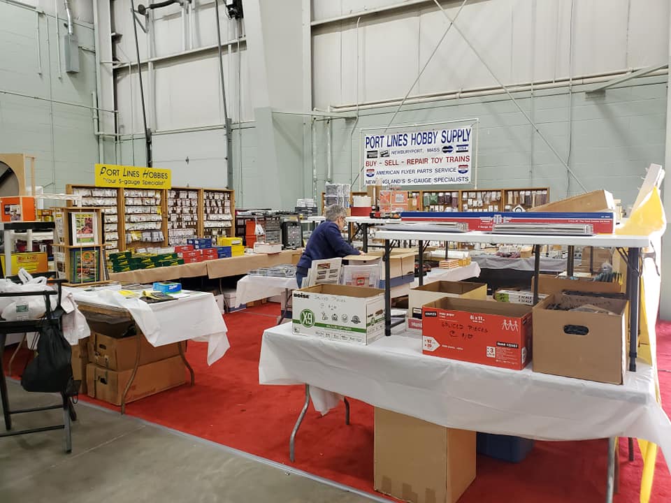
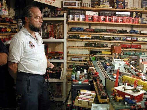
Port Lines has been in the "S" business since about 1985. It initially began as an off-shoot to our own collecting of American Flyer trains. Realizing at local train shows and NETCA meets that no one had AF repair parts available for sale, I began to stock and offer a very limited supply of a handful of commonly needed parts; I sold these from my single table at train shows.....all of these parts hanging from a single piece of pegboard about 2' x 3' in size! Such an assortment !
I have grown to the point that today, I believe I offer one of the largest varieties of AF repair and restoration supplies and parts available anywhere in the country!
QUALITY is foremost in my product line. I will not stock lesser-quality parts just because they are cheaper. I carry the best quality part available, even if it means a slightly higher price.
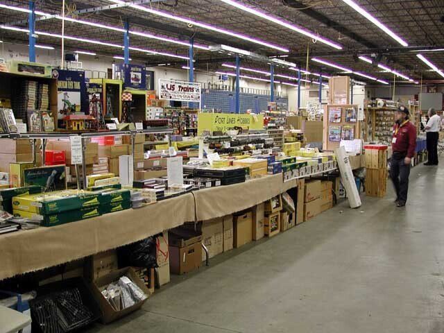
In addition to the AF parts segment of my business, I stock products from a large number of S suppliers and manufacturers.
Any questions.... drop me an
Email.
I'll do what I can to assist you and meet your S needs !
Shop with Confidence
Carefully Selected Products
We personally test and review every product that we sell. We never compromise on quality.
Committed to Customer Service
Our call center is open daily so you can inquire about products and stock, track your package, and more.
Secure Payment Processing
Our site and payment process is secure, so you don't need to worry about protecting your ID.
Your purchase is secure
Satisfaction guaranteed
International shipping
HOME
6 Storeybrooke Drive
Newburyport, MA 01950-3408
Email Doug
888-708-0782 (from US only)
978-465-8798 (International)
Phone calls: 2-5 PM Eastern
Time, Tue-Thu only
Website & Hosting by SovoWeb a division of RedXWebDesign